the12volt.com spacer
icon

1998 Cavalier, alarm/remote start


Post ReplyPost New Topic
< Prev Topic Next Topic >
black cavy 
Copper - Posts: 78
Copper spacespace
Joined: July 24, 2006
Location: Ontario, Canada
Posted: November 22, 2006 at 9:24 AM / IP Logged  
KarTuneMan wrote:

The key sence on this rig is in the black conector on the ign. harness.

Your trunk pop only comes on the cars with keyless entry (factory) it's found in the trunk. Behind carpet left sied of trunk. blk/wht POS(+)

So i do have to remove the platic shield all around the steering wheel to get those wires

Big Dog 
Gold - Posts: 1,265
Gold spaceThis member consistently provides reliable informationspace
Joined: May 02, 2002
Location: Quebec, Canada
Posted: November 22, 2006 at 9:39 AM / IP Logged  

 No. there's an inch and a half gap between steering shroud and dash. Reach in with your finger. It's easier if you remove the 9/32 screws though.

Prepare your future. It wasn't the lack of stones that killed the stone age.
master5 
Silver - Posts: 1,123
Silver spacespace
Joined: October 10, 2006
Location: United States
Posted: November 22, 2006 at 6:15 PM / IP Logged  

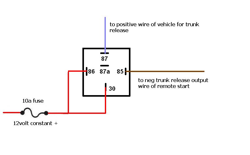
This is the correct relay diagram for your setup.

1998 Cavalier, alarm/remote start - Page 2 -- posted image.

master5 
Silver - Posts: 1,123
Silver spacespace
Joined: October 10, 2006
Location: United States
Posted: November 22, 2006 at 6:21 PM / IP Logged  

BTW chances are 99 out of a hundred if the vehicle used a negative for trunk pop it would be before the factory relay and no additional relay world be required if the system has a negative output. If it needed a relay you would simple use the same diagram I posted but put 30 to ground.

Now if the RS system had a positive output for trunk pop it most likely would not need a relay to pop a positive trunk but you would need to check the particular system to make sure its output current is enough. Some systems have a built in relay for trunk pop and you can choose positive or negative without needing any external relays.

black cavy 
Copper - Posts: 78
Copper spacespace
Joined: July 24, 2006
Location: Ontario, Canada
Posted: November 23, 2006 at 7:42 PM / IP Logged  

Hello all,well i've installed acuple passlock 2 DEI 555l units awhile ago and im having  a little problem with this one passlock 1.

First off i've done all the searches and all the links people give say you have to messure the R-code.But i could swear that the DEI 555L is self learning.

The wires i don't understand are

1,yellow R-code as to my question above^^^

2,Violet

I understand the Ign,red(12v),black and yellow, and the bulb check wire and black wire

But im haveing a hard time understanding what Violet does and do i have to messure the R code

Also is that the Ribbon they speak off,and thats the bulb check right(black wire)

1998 Cavalier, alarm/remote start - Page 2 -- posted image.

1998 Cavalier, alarm/remote start - Page 2 -- posted image.

black cavy 
Copper - Posts: 78
Copper spacespace
Joined: July 24, 2006
Location: Ontario, Canada
Posted: November 24, 2006 at 9:19 PM / IP Logged  
Can i have a hand on this passlock thing please
master5 
Silver - Posts: 1,123
Silver spacespace
Joined: October 10, 2006
Location: United States
Posted: November 24, 2006 at 9:34 PM / IP Logged  

Yes the 555L is self learning..that is what the "L" means.

I think you might be reading too much into it..the only wires that you need to use is 12, the blue wire goes to negative activate RS, and you connect the yellow and yellow black to the yellow you cut from the passlock, and the black goes to the black of the passlock.

you probably don't need to use the violet wire but if you post exactly what it says about this violet wire I will explain what it is for.

The directions on the 555L are confusing at first but on the second page of the wiring it should explain the exact colors for your particular vehicle, and which wires you need and don't need...I know you never need all of them on PK 1's.

black cavy 
Copper - Posts: 78
Copper spacespace
Joined: July 24, 2006
Location: Ontario, Canada
Posted: November 25, 2006 at 2:28 PM / IP Logged  

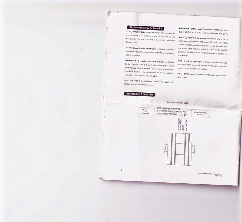
Heres the book,still not to sure what the Violet goes too.It says i need it for passlock 1 thow

1998 Cavalier, alarm/remote start - Page 2 -- posted image.

Sorry but your going to have to zoom in on the picture

master5 
Silver - Posts: 1,123
Silver spacespace
Joined: October 10, 2006
Location: United States
Posted: November 25, 2006 at 4:18 PM / IP Logged  

ok..you connect it to the violet wire on the ribbon cable..thats the multi colored ribbon the plugs in the brain..then to a small modlue..then to the relay pack.  Just strip back the insulation and solder it to the violet on that cable..insulate and you are done.

This sends a negative to the 555L from the starter relay..I don't fully know why it needs this as the blue black is also negative status but I use these for the PK2 alot more so I am not that familiar.

But just do as it says and it should work fine.

master5 
Silver - Posts: 1,123
Silver spacespace
Joined: October 10, 2006
Location: United States
Posted: November 25, 2006 at 4:24 PM / IP Logged  

Oh BTW..my reply was assuming you are installing a DEI R/S. If not you will use a relay to perform this function.

Wire as follows...

30 and 85 to ground

86 to the crank output wire of RS (12v+ during start only)

87 to the violet wire of the 555L

If the system you are installing has a negative output during crank wire (many do just for this purpose), then you can connect that directly to the violet of the 555L and no relay is required.

Hope I helped.

Page of 3

  Printable version Printable version Post ReplyPost New Topic
You cannot post new topics in this forum
You cannot reply to topics in this forum
You cannot delete your posts in this forum
You cannot edit your posts in this forum
You cannot create polls in this forum
You cannot vote in polls in this forum

  •  
Search the12volt.com
Follow the12volt.com Follow the12volt.com on Facebook
Monday, April 29, 2024 • Copyright © 1999-2024 the12volt.com, All Rights Reserved Privacy Policy & Use of Cookies
Disclaimer: *All information on this site ( the12volt.com ) is provided "as is" without any warranty of any kind, either expressed or implied, including but not limited to fitness for a particular use. Any user assumes the entire risk as to the accuracy and use of this information. Please verify all wire colors and diagrams before applying any information.

Secured by Sectigo
the12volt.com spacer
Support the12volt.com
Top
the12volt.com spacer