the12volt.com spacer
icon

need a wiring diagram for 07 ion


Post ReplyPost New Topic
< Prev Topic Next Topic >
Fosgate3 
Copper - Posts: 328
Copper spaceThis member has made a donation to the12volt.com. Click here for more info.spacespace
Joined: January 29, 2004
Location: Louisiana, United States
Posted: June 07, 2007 at 5:34 PM / IP Logged  

Pretty sure of it... under the steering column, about 2 inches from the cylinder: there is a green plug with five 18gauge wires in it: orange, blue, brown, white, and WHITE/ black. The orange is 12v, the blue is ignition, the brown is accessory, the white and WHITE/ black are the passlock wires.

I did notice that with the main resistence wire cut (that would be the solid white one), the security light came on and stayed on in the instrument cluster. When I attached the wires back together and restarted the vehicle, the light went off.

I thought about doing it the "old fashion way" by calculating the resistence. With the red probe of the DMM on the key side of the resistence wire and the black probe on the ground reference wire, the resistence was 1.24kOhm. When the probes were swapped, the resistence was 1.214kOhm. I supposed I could do it that way but I still have to find out why/how to get the remote start to actually start the vehicle. I suppose to make sure the alarm is doing what it's supposed to do is to test for 12v on the pink ignition wire when the remote start is activated, right?

Fosgate3 
Copper - Posts: 328
Copper spaceThis member has made a donation to the12volt.com. Click here for more info.spacespace
Joined: January 29, 2004
Location: Louisiana, United States
Posted: June 07, 2007 at 5:38 PM / IP Logged  
Btw, I saw your post dea,can after I replied. Thanks for the image. Those are the wires I am using. I have ignition1 of the code alarm ca670 going to the blue wire of that harness, the Accessory1 wire going to the brown wire and I'm using the white and wht/black wires for the 555L.
dea,can 
Copper - Posts: 284
Copper spacespace
Joined: January 12, 2006
Location: Saskatchewan, Canada
Posted: June 08, 2007 at 2:56 AM / IP Logged  
i grab my ign wires from dkp pink ign,brown for acc
dragon
Fosgate3 
Copper - Posts: 328
Copper spaceThis member has made a donation to the12volt.com. Click here for more info.spacespace
Joined: January 29, 2004
Location: Louisiana, United States
Posted: June 08, 2007 at 5:16 AM / IP Logged  
what does dkp stand for? so you aren't using the blue wire in that harness (the one in the picture)?
rudydapimp 
Copper - Posts: 390
Copper spacespace
Joined: February 27, 2006
Location: United States
Posted: June 08, 2007 at 8:01 AM / IP Logged  
drivers kick panel = dkp
Fosgate3 
Copper - Posts: 328
Copper spaceThis member has made a donation to the12volt.com. Click here for more info.spacespace
Joined: January 29, 2004
Location: Louisiana, United States
Posted: June 08, 2007 at 8:22 AM / IP Logged  

Okay. I can go look for that now and see if it works better for the remote start than the blue.

Given the mess that I am going through with the 555L, do you think I should start soldering resistors together to get 1.24kOhms? Radio Shack opens in 45mins and I can run up there and start picking out some stuff. If I did this, would I shoot for the 1.24 reading or the 1.214 reading (as I posted above)?

Fosgate3 
Copper - Posts: 328
Copper spaceThis member has made a donation to the12volt.com. Click here for more info.spacespace
Joined: January 29, 2004
Location: Louisiana, United States
Posted: June 08, 2007 at 7:14 PM / IP Logged  

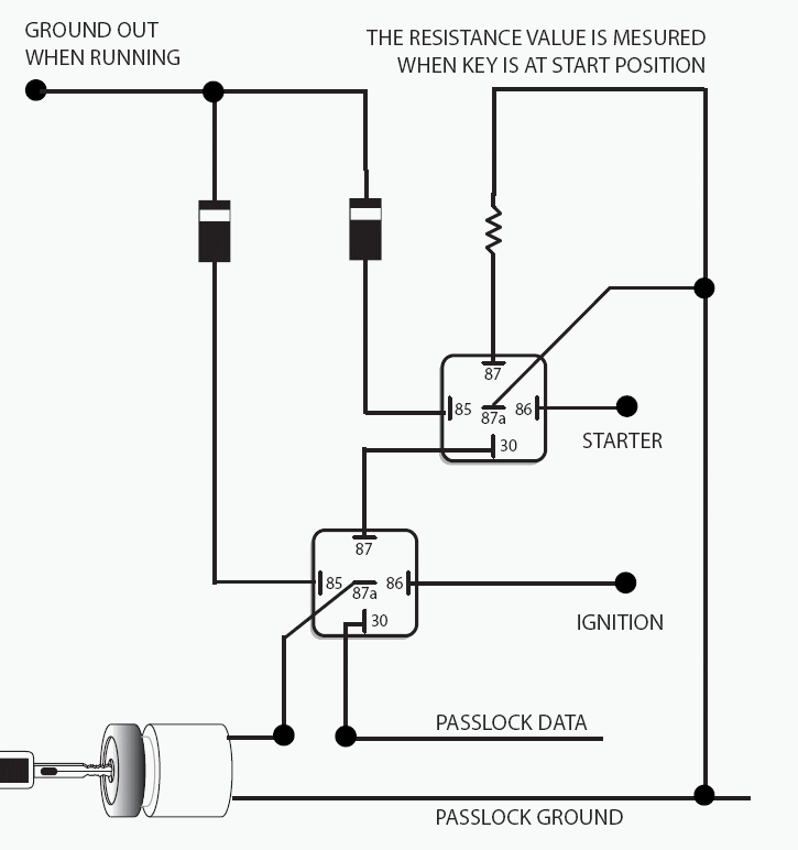
I looked for a pink wire in the dkp and found only one there. However, it does not measure 12volts with the key on, only 6 to 7 volts. It will keep this voltage while starting but still, its not anything close to 12. Since there wasnt any replies stating otherwise and since I cant get anywhere with the 555L module, I made a relay pack out of two relays using the resistence value 1.24kOhms. I found the diagram while research in this website, under a post regarding the same type of setup in a 2005 Canyon. When installed, the car will start with the key. However, i am having a lot of trouble trying to get the remote start part of the alarm to work. I dont know if I have something connected incorrectly or if the alarm is at fault.

Right now, I am not using the ignition2, acc2, or either of the starter wires (keyside and motor side) of the alarm. Should I be?

dea,can 
Copper - Posts: 284
Copper spacespace
Joined: January 12, 2006
Location: Saskatchewan, Canada
Posted: June 09, 2007 at 2:31 AM / IP Logged  
need a wiring diagram for 07 ion - Page 3 -- posted image.
dragon
dea,can 
Copper - Posts: 284
Copper spacespace
Joined: January 12, 2006
Location: Saskatchewan, Canada
Posted: June 09, 2007 at 2:40 AM / IP Logged  
never had trouble with the ions i use kits from bypasskits.com. i dont deal with DEI 556L is what u should be using The 556LW covers all 555LW vehicle applications and includes a built-in relay for compatibility with Colorado, Cobalt, Canyon, and Ion.
dragon
Fosgate3 
Copper - Posts: 328
Copper spaceThis member has made a donation to the12volt.com. Click here for more info.spacespace
Joined: January 29, 2004
Location: Louisiana, United States
Posted: June 09, 2007 at 6:57 AM / IP Logged  
thanks for the diagram. that's pretty much what i found before. Where do you get your starter wire from?
Page of 4

  Printable version Printable version Post ReplyPost New Topic
You cannot post new topics in this forum
You cannot reply to topics in this forum
You cannot delete your posts in this forum
You cannot edit your posts in this forum
You cannot create polls in this forum
You cannot vote in polls in this forum

  •  
Search the12volt.com
Follow the12volt.com Follow the12volt.com on Facebook
Monday, April 29, 2024 • Copyright © 1999-2024 the12volt.com, All Rights Reserved Privacy Policy & Use of Cookies
Disclaimer: *All information on this site ( the12volt.com ) is provided "as is" without any warranty of any kind, either expressed or implied, including but not limited to fitness for a particular use. Any user assumes the entire risk as to the accuracy and use of this information. Please verify all wire colors and diagrams before applying any information.

Secured by Sectigo
the12volt.com spacer
Support the12volt.com
Top
the12volt.com spacer