the12volt.com spacer
icon

reverse voltage for boat


Post ReplyPost New Topic
< Prev Topic Next Topic >
nathan909 
Member - Posts: 12
Member spacespace
Joined: September 29, 2004
Posted: June 29, 2007 at 4:18 PM / IP Logged  
Ok, I have a boat... On it there is a hatch that is motor driven. This motor works off of 2 wires (reverse polarity for down). The system works fine but slow... The voltages runs up to a switch and then back to the motor, about 18'.
The battery is right next to the motor. I would like to add a relay or two, grabbing fused power from the battery 6" away and use that to power the motor. The relays would need to be switch using 2 wires (with reverse polarity for down).
In a nut shell i just want to reproduce the same voltage at the back of the boat, 2 wire, normal polarity or reversed polarity.
Thanks for your help.
-Nathan
KarTuneMan 
Platinum - Posts: 7,056
Platinum spaceThis member has made a donation to the12volt.com. Click here for more info.spaceThis member consistently provides reliable informationspace
Joined: December 14, 2004
Location: Isle Of Man
Posted: June 29, 2007 at 5:45 PM / IP Logged  

I'm confused.... but look here.

https://www.the12volt.com/relays/relays.asp

nathan909 
Member - Posts: 12
Member spacespace
Joined: September 29, 2004
Posted: June 29, 2007 at 6:45 PM / IP Logged  
I have 2 wires with both reg and rev polarity...
I would like to run a higher amp by using relays.
How can i get a relay(s) to supply a motor with both reg and rev polarity.
The Trigger for the relay is 2 wires... sending both reg and rev polarity.
dualsport 
Silver - Posts: 983
Silver spacespace
Joined: September 27, 2005
Location: United States
Posted: June 29, 2007 at 8:55 PM / IP Logged  
Start with this
Start with Hotwaterwizard's diagram, supplying the key switch input with one side of your two wires (pick whichever one gives you the right polarity on the output.)
Then add another relay to break the 12V input, with the coil connected to your two wires, so that it only closes when you have either a reg or rev polarity signal going in (make sure your relay doesn't have any built in suppression diodes, since it needs to work with both directions.
hotwaterwizard 
Silver - Posts: 1,350
Silver spacespace
Joined: December 11, 2003
Location: California, United States
Posted: June 30, 2007 at 12:23 AM / IP Logged  
reverse voltage for boat -- posted image.
John DeRosa (Hotwaterwizard)
Stockton California
When in doubt, try it out !
hotwaterwizard 
Silver - Posts: 1,350
Silver spacespace
Joined: December 11, 2003
Location: California, United States
Posted: June 30, 2007 at 12:32 AM / IP Logged  
The circuit Above will only work if there are Limit switches built into the Actuators.
John DeRosa (Hotwaterwizard)
Stockton California
When in doubt, try it out !
hotwaterwizard 
Silver - Posts: 1,350
Silver spacespace
Joined: December 11, 2003
Location: California, United States
Posted: June 30, 2007 at 12:42 AM / IP Logged  

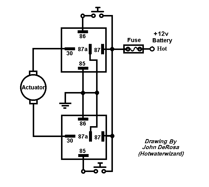
Here is a circuit that you can use push button switches and 3 wires.

This one will work with motors that do not have limit switches.

reverse voltage for boat -- posted image.

John DeRosa (Hotwaterwizard)
Stockton California
When in doubt, try it out !
dualsport 
Silver - Posts: 983
Silver spacespace
Joined: September 27, 2005
Location: United States
Posted: June 30, 2007 at 9:11 AM / IP Logged  

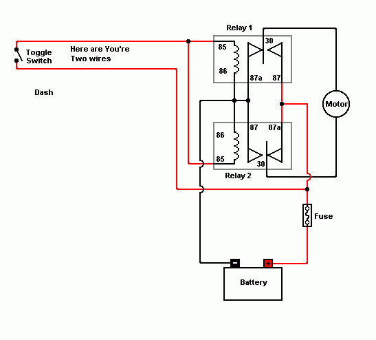
reverse voltage for boat -- posted image.

This is what I had in mind, using the two existing wires for controlling the relays.

hotwaterwizard 
Silver - Posts: 1,350
Silver spacespace
Joined: December 11, 2003
Location: California, United States
Posted: June 30, 2007 at 11:48 AM / IP Logged  

Oh just cut the power to the circuit to stop the motor but how do you make the switch from open to close with this setup?

John DeRosa (Hotwaterwizard)
Stockton California
When in doubt, try it out !
dualsport 
Silver - Posts: 983
Silver spacespace
Joined: September 27, 2005
Location: United States
Posted: June 30, 2007 at 12:31 PM / IP Logged  

The two wires he already has running to the motor are reversing polarity wires.  During the off condition, there's no voltage on any of the wires, all the relays are deenergized, and nothing is powered up.  He just needs a boost in power using relays, because there's currently a big drop from the long length of wires he's running.

The Input (+) and Input (-) become inverted when he closes the hatch, and result in the two relays going into the reverse polarity configuration.

  • Standby:  Input(+) = 0V,   Input(-) = 0V   Relays off, no power to motor
  • Open Hatch: Input(+) = 12V,   Input(-) = GND   Polarity configuration relays ON, 12V power relay ON, Positive polarity power to motor
  • Close Hatch: Input(+) = GND,   Input(-) = 12V   Polarity configuration relays OFF, 12V power relay ON, Negative polarity power to motor
Page of 3

  Printable version Printable version Post ReplyPost New Topic
You cannot post new topics in this forum
You cannot reply to topics in this forum
You cannot delete your posts in this forum
You cannot edit your posts in this forum
You cannot create polls in this forum
You cannot vote in polls in this forum

  •  
Search the12volt.com
Follow the12volt.com Follow the12volt.com on Facebook
Thursday, October 10, 2024 • Copyright © 1999-2024 the12volt.com, All Rights Reserved Privacy Policy & Use of Cookies
Disclaimer: *All information on this site ( the12volt.com ) is provided "as is" without any warranty of any kind, either expressed or implied, including but not limited to fitness for a particular use. Any user assumes the entire risk as to the accuracy and use of this information. Please verify all wire colors and diagrams before applying any information.

Secured by Sectigo
the12volt.com spacer
Support the12volt.com
Top
the12volt.com spacer