


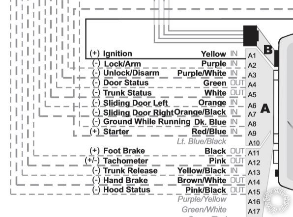
 Lock is the Purple wire at Pin A2
Unlock is Purple/White at Pin A3
Tach is at the Pink wire at Pin A12
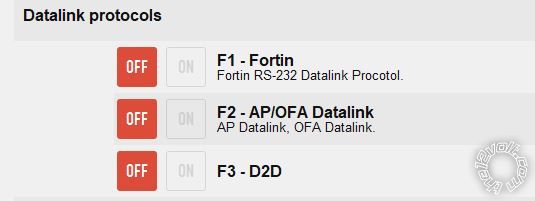
If Code Alarm systems only support Flashlogic bypass modules which use the DBI protocol, then you would need to set the EVO-ALL Option F3 as shown below :
Lock is the Purple wire at Pin A2
Unlock is Purple/White at Pin A3
Tach is at the Pink wire at Pin A12
If Code Alarm systems only support Flashlogic bypass modules which use the DBI protocol, then you would need to set the EVO-ALL Option F3 as shown below :
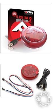
 This is done using the Fortin FlashLink2 cable pictured below :
 But to finally answer your question, here is the info you requested :
Lock VIOLET\DK GREEN (- 330 OHMS) DRIVER KICK
Unlock SAME AS LOCK WIRE (- 100 OHMS)DRIVER KICK
This is a one wire multiplex lock system. You might need two relays besides the listed value resistors to make it work.
Tach Signal NOT BROWN\WHITE ANY FUEL INJECTOR
But to finally answer your question, here is the info you requested :
Lock VIOLET\DK GREEN (- 330 OHMS) DRIVER KICK
Unlock SAME AS LOCK WIRE (- 100 OHMS)DRIVER KICK
This is a one wire multiplex lock system. You might need two relays besides the listed value resistors to make it work.
Tach Signal NOT BROWN\WHITE ANY FUEL INJECTOR Printable version


| You cannot post new topics in this forum You cannot reply to topics in this forum You cannot delete your posts in this forum You cannot edit your posts in this forum You cannot create polls in this forum You cannot vote in polls in this forum |

| Search the12volt.com |
Follow the12volt.com 
Tuesday, May 12, 2026 • Copyright © 1999-2026 the12volt.com, All Rights Reserved • Privacy Policy & Use of Cookies

Tuesday, May 12, 2026 • Copyright © 1999-2026 the12volt.com, All Rights Reserved • Privacy Policy & Use of Cookies
Disclaimer:
*All information on this site ( the12volt.com ) is provided "as is" without any warranty of any kind, either expressed or implied, including but not limited to fitness for a particular use. Any user assumes the entire risk as to the accuracy and use of this information. Please
verify all wire colors and diagrams before applying any information.
