the12volt.com spacer
icon

2010 ford fusion heated seats


Post ReplyPost New Topic
< Prev Topic Next Topic >
and_fis 
Member - Posts: 11
Member spacespace
Joined: November 27, 2012
Location: Illinois, United States
Posted: December 06, 2012 at 2:46 PM / IP Logged  
I am using an audiovox aps901c. The aux line is a neg output. The heated seats trigger is also a neg it is located behind the switch on the dash. When you press the button it sends a pluse and activates the heated seats. Now I have gotten this to work by taking a ground wire and touching the heated seat wire and it turns on. But, I'm needing a relay to do it from the aux channel of the remote start. Anyone have a diagram? Neg switched to a neg pulse?
and_fis 
Member - Posts: 11
Member spacespace
Joined: November 27, 2012
Location: Illinois, United States
Posted: December 06, 2012 at 4:03 PM / IP Logged  
2010 ford fusion heated seats -- posted image.
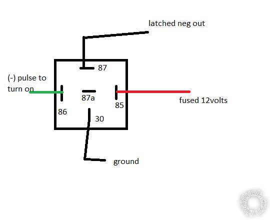
would this set up work? and would I need a resistor of some sorts on the neg out. I have read a few other ford posts about trucks that have neg seat wires. They say it needs to be a latched output and not a pulsed output. I'm guessing the same would go for the 2010 fusion as well?
howie ll 
Pot Metal - Posts: 16,466
Pot Metal spacespace
Joined: January 09, 2007
Location: United Kingdom
Posted: December 06, 2012 at 4:56 PM / IP Logged  
Try using a meter to ground it.
If 100 mamps or less is the draw all you need is your aux connected directly.
If you ground it for say 1 second and it stays on, then a momentary pulse is fine.
Otherwise the relay drawing shown is fine but insert a 1N4004 diode across 85 and 86 with the band towards 86, to protect the R/S.
If you want it latched, use a latched relay say Omron G6AK-234P-12DC
Switch on with the aux, off with say a spur from your vehicle unlock or a second aux.
US suppliers in Mouser, Farnell.
Or of course program the aux as latched with ignition.
howie ll 
Pot Metal - Posts: 16,466
Pot Metal spacespace
Joined: January 09, 2007
Location: United Kingdom
Posted: December 06, 2012 at 5:03 PM / IP Logged  
G6AK should be G6BK sorry.
and_fis 
Member - Posts: 11
Member spacespace
Joined: November 27, 2012
Location: Illinois, United States
Posted: December 06, 2012 at 5:27 PM / IP Logged  

Thank you for your fast reply.. I will try it out this saturday. I am away right now and wont have the time to take the dash apart. I will let your know how it worked out..Also if its above 200 ma when i meter the switch then the relay is a must. I assume thats the 1 amp 1N4004 diode too?

howie ll 
Pot Metal - Posts: 16,466
Pot Metal spacespace
Joined: January 09, 2007
Location: United Kingdom
Posted: December 06, 2012 at 5:38 PM / IP Logged  
Quite correct ref. the relay.
Yes, I regard it as mandatory.
On relay shut down the coil inductance generates an EMP spike of up to 300 volts. The 1N4004 is rated at 400 volts.
It can and does fry the R/S aux and sometimes lock outputs.
Seen it on the forum after people disregard that advice, "oh my locks etc. suddenly don't work".
At least YOU are listening and asking intelligent questions, the type of person it's a joy to help.
Ask away.
and_fis 
Member - Posts: 11
Member spacespace
Joined: November 27, 2012
Location: Illinois, United States
Posted: December 06, 2012 at 5:50 PM / IP Logged  
ahhh... I could see that spike happening in cold weather. Relays have a tendency to wanna stick when they get too cold. You sir have been most helpfull. I have been out of the install scene for about 12 years. This new tech of remote starts are alot nicer compaired to the massive pre-wired relay packs of yester-years. thanks again.
jstruckman 
Copper - Posts: 465
Copper spacespace
Joined: May 03, 2004
Posted: December 07, 2012 at 11:55 AM / IP Logged  
Howie, according to his diagram wouldnt you want the diode with the band toward 85, not 86, since he has +12v on that side. Just a little observation there.
howie ll 
Pot Metal - Posts: 16,466
Pot Metal spacespace
Joined: January 09, 2007
Location: United Kingdom
Posted: December 07, 2012 at 1:11 PM / IP Logged  
Absolutely right!
Sorry about that, on my diagrams I always place 86 to the right.
ISO convention of course also nominates 86 as the POS side of the coil, I know I should have looked 2010 ford fusion heated seats -- posted image.
and_fis 
Member - Posts: 11
Member spacespace
Joined: November 27, 2012
Location: Illinois, United States
Posted: December 08, 2012 at 1:47 AM / IP Logged  
Ok. I wired up the relay. It clicks. The seat light doesn't light up nor heat up. I metered it from the WHITE/ blue wire (driver seat heater) I get 13.75v I press the button it drops to .022 volts then back up to 13.75 volts. Now if I press the button for the heated seats a bunch then when I do a neg pulse it works but as soon as I shut off the vehicle and remote start it the ground pluse doesn't work. Even if I tap the wire with a direct ground source. Nothing. But as soon as I start playing with the button the ground pulse works again. This WHITE/ blue wire is listed as a neg wire. I put the neg side of my fluke meter on the wire and put my pos to ground and I get a -13.75 that tells me it is a neg wire. What am I missing here? Don't understand why it's not turning on with a neg pulse. Is it a neg break maybe? And if so how can you do that with a relay?
Page of 2

  Printable version Printable version Post ReplyPost New Topic
You cannot post new topics in this forum
You cannot reply to topics in this forum
You cannot delete your posts in this forum
You cannot edit your posts in this forum
You cannot create polls in this forum
You cannot vote in polls in this forum

  •  
Search the12volt.com
Follow the12volt.com Follow the12volt.com on Facebook
Saturday, May 11, 2024 • Copyright © 1999-2024 the12volt.com, All Rights Reserved Privacy Policy & Use of Cookies
Disclaimer: *All information on this site ( the12volt.com ) is provided "as is" without any warranty of any kind, either expressed or implied, including but not limited to fitness for a particular use. Any user assumes the entire risk as to the accuracy and use of this information. Please verify all wire colors and diagrams before applying any information.

Secured by Sectigo
the12volt.com spacer
Support the12volt.com
Top
the12volt.com spacer