the12volt.com spacer
icon

strange wiring issue, alarm, 2010 edge


Post ReplyPost New Topic
< Prev Topic Next Topic >
topless stang 
Copper - Posts: 67
Copper spacespace
Joined: April 22, 2012
Location: Kentucky, United States
Posted: October 06, 2012 at 9:04 AM / IP Logged  
kreg357 wrote:

As you figured out on the DMM, the Red lead is connected into the "Volt ohm diode" position for all testing

except actual DC current testing ( 10A DC position).

If I understand you correctly, the Violet/White wire you connected the DMM Red lead to does give the correct

+12V response when you turn the Headlight switch to the Parking Light position.  The fact that it also gives
a +12V reading when you press Lock or Unlock on the CA6552's FOB's is because the CA6552's Parking Light
White output wire is connected to the Violet/White wire and suppling that voltage/signal. 

The clicking noise from the CA6552 is its' internal relays, probably the Parking Light relay in this case.

A few questions.

Do all of the functions on the Edge work normally?  The parking Lights work as they should via the

Headlight switch.  The door locks work normally via the door control buttons and the Factory FOB. Etc...
You don't want to be chasing your tail thinking the problem is the CA6552 install when it's a vehicle
problem.  If there are any issues, remove the CA6552 completely and see if they still exist.  Make the
vehicle work 100% before attempting the R/S install.

While it is a pain ( a lot of typing ), listing all of your wiring from the CA6552 harnesses to the vehicle

connection point ( wire name, color, location ) would help.

While the DMM testing previously described is used for (+) wires, a slightly different method is used to

test / identify (-) wires ( like the door lock, unlock, horn, door triggers, etc ).  Basically, the test
leads are reversed.  The Red lead will connect to a know +12V constant source and the Black test lead will
be used to probe / test the suspect wire.  Once again the DMM will show +12V when the suspect wires' signal
is present.  ( It is showing +12V, not the negative signal, because it sees +12V when the suspect wire goes
to ground (-) and completes the circuit. )  If you connect the DMM this way and test the CA6552s' Lock
output, it will show +12V for the brief 0.8 second output duration.

This is turning into a nightmare install...I thanks everyone for their help thus far. Now for the info you asked for...
4 Pin Main Harness
WHITE/ red - Parking Light (+)
White - Blue/Red wire on Ignition Harness
Black - Ground Screw on Chassis
6 Pin Start Harness
Purple - Starter output (Motor Side) - Blue/White wire on Ignition Harness
Red - Blue/Red wire on Ignition Harness
Orange - PURPLE / Green Accessory wire - Ignition Harness
RED / White - Blue/Red wire on Ignition Harness
Pink - WHITE/ Orange wire on Ignition Harness
6 Pin Output Harness
RED / White - Grey / YELLOW Wire at truck switch on dash
Orange - connected to to Starter Kill Relay
8 Pin Input Harness
Purple - Gray/Purple wire SJB Plug A
Gray - Blue/Orange Wire in Driver side kick
BLACK/ white - blue/gray SJB Plug C
BROWN / Red - PURPLE / White SJB Plug B
3 Pin Lock Output Harness
Green - Gray / YELLOW SJB Plug C
Blue - PURPLE / Gray SJB Plug C
Now as far as the car goes everything works...
Car Starts with Key
Doors lock and Unlock via switch
Trunk opens and closes via switch
All lights function properly
Alarm functions
Door locks and unlocks properly
Siren chirps
Truck opens and closes via alarm fob
Alarm issues
Parking lights do not flash - when the lights are supposed to flash the interior lights Do flash, however, the instrument cluster does not flash along with the other lights on the dash/steering wheel.
Remote start does not attempt to start the car, the interior lights flicker 3 times, which if it is the correct number it points to an issue with one or all of the connections below:
1. Brake (+)
2. E-Brake (-)
3. Hood Pin (-)
I checked all three connections about three times now. At first I just connected the e-brake & hood pin connections to Ground, but I changed that and made the actual connections, but the result is the same. If it matters I do have the FLCAN connected, but not fully programmed.
I think that's it...let me know what other questions you may have.
kreg357 
Platinum - Posts: 7,783
Platinum spaceThis member has made a donation to the12volt.com. Click here for more info.spaceThis member has been recognized as an authority in Electrical Theory. Click here for more info.spaceThis member has been recognized as an authority in Mobile Security and Convenience. Click here for more info.spacespace
Joined: January 30, 2009
Location: Pennsylvania, United States
Posted: October 06, 2012 at 9:28 AM / IP Logged  

Unless this was a typo, it looks like you have these backwards :

4 Pin Main Harness
WHITE/ red - Parking Light (+)
White - Blue/Red wire on Ignition Harness
Black - Ground Screw on Chassis

The WHITE/ Red wire should have the +12V constant power and the White wire is the CA6552s' output that

gets connected to the Edges' Violet/White (+) Parking Light wire.

Soldering is fun!
topless stang 
Copper - Posts: 67
Copper spacespace
Joined: April 22, 2012
Location: Kentucky, United States
Posted: October 06, 2012 at 9:41 AM / IP Logged  
kreg357 wrote:

Unless this was a typo, it looks like you have these backwards :

4 Pin Main Harness
WHITE/ red - Parking Light (+)
White - Blue/Red wire on Ignition Harness
Black - Ground Screw on Chassis

The WHITE/ Red wire should have the +12V constant power and the White wire is the CA6552s' output that

gets connected to the Edges' Violet/White (+) Parking Light wire.

Geez, sorry..it was a typo, I can't believe I missed that.WHITE/ red is connected to constant hot.
kreg357 
Platinum - Posts: 7,783
Platinum spaceThis member has made a donation to the12volt.com. Click here for more info.spaceThis member has been recognized as an authority in Electrical Theory. Click here for more info.spaceThis member has been recognized as an authority in Mobile Security and Convenience. Click here for more info.spacespace
Joined: January 30, 2009
Location: Pennsylvania, United States
Posted: October 06, 2012 at 9:48 AM / IP Logged  

The failure to remote start is from the Hood Pin input.  The Edge has N.C. status wires.  You will need to install the Hood Pin supplied with the CA6552 because it can't be programmed for N.C. inputs.  You can temporarily disconnect it to see if the remote start function will work ( or just open the hood ).

CA6552  Gray wire at 8 Pin Input harness.

What are you using as a bypass module?

Did you set the CA6552 for Tachless operation?

Soldering is fun!
topless stang 
Copper - Posts: 67
Copper spacespace
Joined: April 22, 2012
Location: Kentucky, United States
Posted: October 06, 2012 at 9:57 AM / IP Logged  
kreg357 wrote:

The failure to remote start is from the Hood Pin input.  The Edge has N.C. status wires.  You will need to install the Hood Pin supplied with the CA6552 because it can't be programmed for N.C. inputs.  You can temporarily disconnect it to see if the remote start function will work ( or just open the hood ).

CA6552  Gray wire at 8 Pin Input harness.

What are you using as a bypass module?

Did you set the CA6552 for Tachless operation?

I tired with hood pin disconnected multiple times (Hood both closed and open), but I ended up connecting it after getting this error as the manual says its a mandatory connection. It won't work if its tied directly to ground?
kreg357 
Platinum - Posts: 7,783
Platinum spaceThis member has made a donation to the12volt.com. Click here for more info.spaceThis member has been recognized as an authority in Electrical Theory. Click here for more info.spaceThis member has been recognized as an authority in Mobile Security and Convenience. Click here for more info.spacespace
Joined: January 30, 2009
Location: Pennsylvania, United States
Posted: October 06, 2012 at 10:16 AM / IP Logged  

No, a ground signal on that Gray wire will indicate an open Hood and prevent a remote start.  The Hood Pin input is a very important safety feature.  Whereas a ground signal is necessary on the BLACK/ White Neutral Safety wire to allow a remote start.  Guess you will have to use the DMM on each of those inputs to see which one is causing the failed remote start.

Soldering is fun!
topless stang 
Copper - Posts: 67
Copper spacespace
Joined: April 22, 2012
Location: Kentucky, United States
Posted: October 06, 2012 at 10:44 AM / IP Logged  
kreg357 wrote:

No, a ground signal on that Gray wire will indicate an open Hood and prevent a remote start.  The Hood Pin input is a very important safety feature.  Whereas a ground signal is necessary on the BLACK/ White Neutral Safety wire to allow a remote start.  Guess you will have to use the DMM on each of those inputs to see which one is causing the failed remote start.

Ok, from what I read the hood pin install doesn't look too ba. Any thoughts about the parking lights
kreg357 
Platinum - Posts: 7,783
Platinum spaceThis member has made a donation to the12volt.com. Click here for more info.spaceThis member has been recognized as an authority in Electrical Theory. Click here for more info.spaceThis member has been recognized as an authority in Mobile Security and Convenience. Click here for more info.spacespace
Joined: January 30, 2009
Location: Pennsylvania, United States
Posted: October 06, 2012 at 11:51 AM / IP Logged  

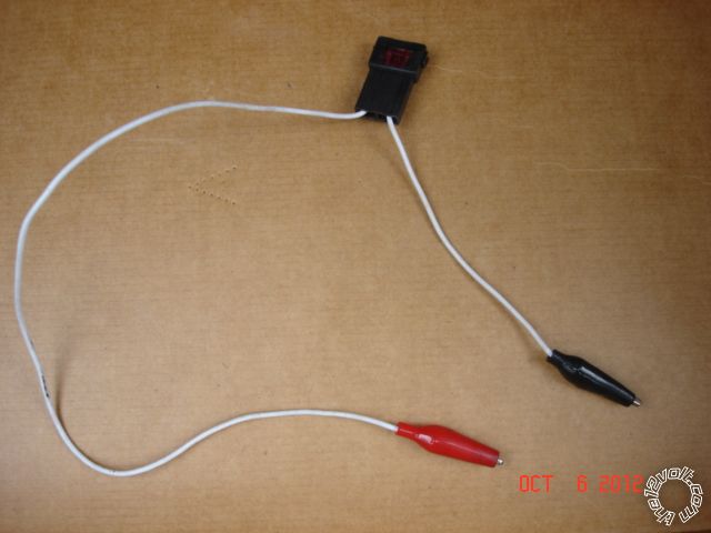
My usual way to locate, verify and test the Parking Light includes using a fused jumper cable to actually turn the Parking Lights on manually after making very sure I am on the correct wire.   In this case going from +12V constant to the Violet/White (+) Parking Light wire.

strange wiring issue, alarm, 2010 edge - Page 6 -- posted image.

Soldering is fun!
topless stang 
Copper - Posts: 67
Copper spacespace
Joined: April 22, 2012
Location: Kentucky, United States
Posted: October 06, 2012 at 12:12 PM / IP Logged  
kreg357 wrote:

No, a ground signal on that Gray wire will indicate an open Hood and prevent a remote start.  The Hood Pin input is a very important safety feature.  Whereas a ground signal is necessary on the BLACK/ White Neutral Safety wire to allow a remote start.  Guess you will have to use the DMM on each of those inputs to see which one is causing the failed remote start.

If the default setting of a properly installed switch is 'Open', then is it even necessary to have a working remote start? I would rather the remote start worked with the hood open anyway. Is that possible?
topless stang 
Copper - Posts: 67
Copper spacespace
Joined: April 22, 2012
Location: Kentucky, United States
Posted: October 06, 2012 at 12:16 PM / IP Logged  
kreg357 wrote:

My usual way to locate, verify and test the Parking Light includes using a fused jumper cable to actually turn the Parking Lights on manually after making very sure I am on the correct wire.   In this case going from +12V constant to the Violet/White (+) Parking Light wire.

strange wiring issue, alarm, 2010 edge - Page 6 -- posted image.

So by using this I would connect one end to one of the constant hot wires and the other to the parking light wire? I'll try that. Something is just amiss because some of the interior lights do flash like they're supposed to (ie - steering wheel lights & HVAC control lights), so I was sure it was wired up correctly.
Page of 8

  Printable version Printable version Post ReplyPost New Topic
You cannot post new topics in this forum
You cannot reply to topics in this forum
You cannot delete your posts in this forum
You cannot edit your posts in this forum
You cannot create polls in this forum
You cannot vote in polls in this forum

  •  
Search the12volt.com
Follow the12volt.com Follow the12volt.com on Facebook
Saturday, April 27, 2024 • Copyright © 1999-2024 the12volt.com, All Rights Reserved Privacy Policy & Use of Cookies
Disclaimer: *All information on this site ( the12volt.com ) is provided "as is" without any warranty of any kind, either expressed or implied, including but not limited to fitness for a particular use. Any user assumes the entire risk as to the accuracy and use of this information. Please verify all wire colors and diagrams before applying any information.

Secured by Sectigo
the12volt.com spacer
Support the12volt.com
Top
the12volt.com spacer