the12volt.com spacer
icon

1999 dodge ram door locks


Post ReplyPost New Topic
< Prev Topic Next Topic >
JWorm 
Platinum - Posts: 2,208
Platinum spacespace
Joined: December 11, 2002
Location: New Hampshire, United States
Posted: December 20, 2007 at 4:48 PM / IP Logged  
You should be testing for "switch" side when only 1 wire (the wire you are testing) is cut. Cutting both wires and then testing for "switch side" may give you misleading results.
ralphtonka 
Member - Posts: 30
Member spacespace
Joined: December 20, 2007
Location: Alberta, Canada
Posted: December 20, 2007 at 10:21 PM / IP Logged  
If factory keyless there will be brown box above gas pedal doorlocks are +, must pull dr door lock sw and install 3A diode on pink purple wire
fingerbang 
Member - Posts: 12
Member spacespace
Joined: December 18, 2007
Location: Manitoba, Canada
Posted: January 05, 2008 at 1:54 PM / IP Logged  
ok now i really need help.
i have followed 3 similar diagrams and they all do pretty much nothing except blow my fuses.
heres what i do:
ORANGE / violet connected
pink/violet cut.
with my tester i connect black to ground and check the pink and violet wires for 12 volts when i hit the UNLOCK SWITCH, 1 of the wires will give me 12 volts on UNLOCK and the other will give me 12volts when i put the switch to LOCK. It will do this for both sets of wires.
IS THIS NORMAL???
I am soo bloody confused. I have verified my wires soo many times and they are correct.
am i using the wrong fuses? they are standard heavy duty 30amp auto relays
JWorm 
Platinum - Posts: 2,208
Platinum spacespace
Joined: December 11, 2002
Location: New Hampshire, United States
Posted: January 05, 2008 at 3:35 PM / IP Logged  
fingerbang wrote:
ok now i really need help.
i have followed 3 similar diagrams and they all do pretty much nothing except blow my fuses.
heres what i do:
ORANGE / violet connected
pink/violet cut.
with my tester i connect black to ground and check the pink and violet wires for 12 volts when i hit the UNLOCK SWITCH, 1 of the wires will give me 12 volts on UNLOCK and the other will give me 12volts when i put the switch to LOCK. It will do this for both sets of wires.
IS THIS NORMAL???
am i using the wrong fuses? they are standard heavy duty 30amp auto relays
Yes, that is normal
Leave the ORANGE / purple connected. Cut the pink/violet. Connect the meter as you have been doing. Hit UNLOCK on the door. If it shows +12v, you have the switch side of the UNLOCK wire. Connect it to 87a of the relay. If it does not show 12v, you have the motor side of the UNLOCK wire. Connect it to 30. You are testing the UNLOCK wire. Pay no attention to what happens when you hit LOCK on the door.
After the pink/violet has been reconnected (or connected to the relay you are installing then you can cut the ORANGE / purple LOCK wire. Test as before, but only hit the LOCK button on the door. The side that shows 12v gets connected to 87a. The other side goes to 30.
I would use a smaller fuse.   Either a 15 or 20 amp fuse. Two doorlock motors should never pull more current than that.
moonliter 
Copper - Posts: 322
Copper spacespace
Joined: February 28, 2007
Location: Canada
Posted: January 05, 2008 at 3:49 PM / IP Logged  

Here is how I would do to find out the switch side and the motor side of the lock & unlock wires.

ORANGE / violet (lock wire), pink/violet (unlock wire) , cut both wires at the driver kick panel, according to my chart, the driver side is the master so you test with the master switch. put the red lead of your dmm on the ORANGE / violet (lock), the black lead on the pink/violet (unlock) on the same side of the cut wires.

Test the side that when you press the lock button, your dmm shows +12v , read -12v when you press the unlock . When proven then this will be your switch side of the lock/unlock wires.

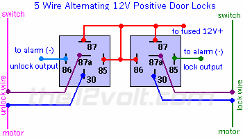
Connect the switch side of ORANGE / violet to 87a of lock relay. the motor side to 30 of the lock relay.  86 & 87 to +12v, 85 to the lock output (-) from rs

Connect the switch side of pink/violet to 87a of the unlock relay. the motor side to 30 of the unlock relay. 86 & 87 to +12v, 85 to the unlock output (-) from rs

fingerbang 
Member - Posts: 12
Member spacespace
Joined: December 18, 2007
Location: Manitoba, Canada
Posted: January 05, 2008 at 4:23 PM / IP Logged  
1999 dodge ram door locks - Page 2 -- posted image.
fingerbang 
Member - Posts: 12
Member spacespace
Joined: December 18, 2007
Location: Manitoba, Canada
Posted: January 05, 2008 at 4:32 PM / IP Logged  
ahhh i cant edit....
unlock side is pink/violet
lock side is ORANGE / violet
with pink/violet cut, and i hit the unlock i can get the 12V+ on one of the 2 wires that is the switch side (87a) of unlock and therefore the other goes to 30 (motor)
with ORANGE / violet cut, and i hit the lock i can get the 12V+ on one of the 2 wires that is the switch side (87a) of lock and therefore the other goes to 30 (motor).
i have wired 100% exactly as above and when i do that, it blows the 12V+ fuse right away, without pressing anything.
but reverse the 87a and 30 on each relay and the fuse does not blow, but lock wont work.
fingerbang 
Member - Posts: 12
Member spacespace
Joined: December 18, 2007
Location: Manitoba, Canada
Posted: January 05, 2008 at 4:36 PM / IP Logged  
fingerbang wrote:
ahhh i cant edit....
unlock side is pink/violet
lock side is ORANGE / violet
with pink/violet cut, and i hit the unlock i can get the 12V+ on one of the 2 wires that is the switch side (87a) of unlock and therefore the other goes to 30 (motor)
with ORANGE / violet cut, and i hit the lock i can get the 12V+ on one of the 2 wires that is the switch side (87a) of lock and therefore the other goes to 30 (motor).
i have wired 100% exactly as above and when i do that, it blows the 12V+ fuse right away, without pressing anything.
but reverse the 87a and 30 on each relay and the fuse does not blow, but lock/unlock wont work.
moonliter 
Copper - Posts: 322
Copper spacespace
Joined: February 28, 2007
Location: Canada
Posted: January 06, 2008 at 10:55 PM / IP Logged  

fingerbang wrote:
i have wired 100% exactly as above and when i do that, it blows the 12V+ fuse right away, without pressing anything.

i hope you didn't connect the 12v+ to pin 30's instead of pin 87 of the relays. that would be a disaster, it will blow the fuse right away.  12v+ must connect to pin 87 of the relay only.

Check your connections of the lock/unlock wires again....

switch side of the lock wire must go to pin 87a, motor side goes to pin 30 of the lock relay.

switch side of the unlock wire must go to pin 87a, motor side goes to pin 30 of the unlock relay.

fingerbang 
Member - Posts: 12
Member spacespace
Joined: December 18, 2007
Location: Manitoba, Canada
Posted: January 07, 2008 at 1:04 AM / IP Logged  
ive wired the relays EXACTLY as above's picture. with 12V+ going to the 4 pins.
Page of 3

  Printable version Printable version Post ReplyPost New Topic
You cannot post new topics in this forum
You cannot reply to topics in this forum
You cannot delete your posts in this forum
You cannot edit your posts in this forum
You cannot create polls in this forum
You cannot vote in polls in this forum

  •  
Search the12volt.com
Follow the12volt.com Follow the12volt.com on Facebook
Thursday, April 18, 2024 • Copyright © 1999-2024 the12volt.com, All Rights Reserved Privacy Policy & Use of Cookies
Disclaimer: *All information on this site ( the12volt.com ) is provided "as is" without any warranty of any kind, either expressed or implied, including but not limited to fitness for a particular use. Any user assumes the entire risk as to the accuracy and use of this information. Please verify all wire colors and diagrams before applying any information.

Secured by Sectigo
the12volt.com spacer
Support the12volt.com
Top
the12volt.com spacer