the12volt.com spacer
icon

pg octane 900.5 repair


Post ReplyPost New Topic
< Prev Topic Next Topic >
ianarian 
Copper - Posts: 516
Copper spacespace
Joined: April 24, 2009
Location: California, United States
Posted: September 15, 2009 at 11:56 PM / IP Logged  
I borrowed some from the lab guy at work... He is from Loiusana too! Tomorrow, I get out the bench and try testing. Do the resistors stay on still? Then what type of test should I do on the transistors? Voltage between center and outer legs?
This is what I do for FUN!
i am an idiot 
Platinum - Posts: 13,667
Platinum spaceThis member consistently provides reliable informationspace
Joined: September 21, 2006
Location: Louisiana, United States
Posted: September 16, 2009 at 12:29 AM / IP Logged  
With the 2 Ohm resistor in series with the power wire, turn the amp on for 10 seconds and check the resistor for heat.  If it is not hot, try it for 20 seconds check temp again.  If possible during the 20 second run, check the voltage on the left leg of each of the power supply transistors.  Black lead on the ground terminal of the amp or the ground terminal of the power supply.  Red lead on the left leg of each transistor.    After you get these voltages, check the resistor for heat again.  It will hopefully be only a few degrees above ambient.  Next time you turn the amp on, check the voltage from the power terminal of the amp to the ground termina of the amp.  Our goal voltage is 12 or so.   Let me know what you come up with.
ianarian 
Copper - Posts: 516
Copper spacespace
Joined: April 24, 2009
Location: California, United States
Posted: September 17, 2009 at 5:34 AM / IP Logged  
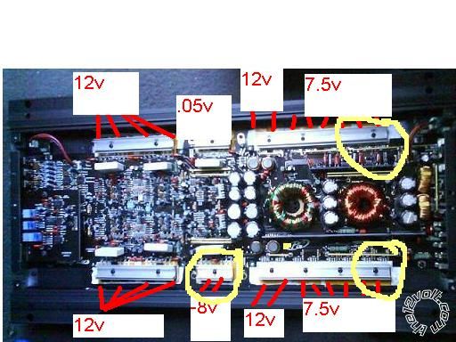
OK Idi, we got 7.5v on the input terminals to the amp...The resistors get pretty warm, but not too hot. All 5a fuses are holding, and the voltage readings are as follows. The yellow circles are the replacements we made.pg octane 900.5 repair - Page 6 -- posted image.
This is what I do for FUN!
i am an idiot 
Platinum - Posts: 13,667
Platinum spaceThis member consistently provides reliable informationspace
Joined: September 21, 2006
Location: Louisiana, United States
Posted: September 17, 2009 at 6:15 AM / IP Logged  
The 7.5 volt reading has to be on the middle leg of the z44s.  What is the voltage on the left leg?  Black lead on ground terminal and red lead on the Left leg of each of the z44s.  Left leg is the leg connected to the resistors you checked earlier.
ianarian 
Copper - Posts: 516
Copper spacespace
Joined: April 24, 2009
Location: California, United States
Posted: September 17, 2009 at 10:05 AM / IP Logged  
Solder High....They all make the same reading, initially like 1.4 then settles into a .05(+/-) on the 20VDC setting.
This is what I do for FUN!
i am an idiot 
Platinum - Posts: 13,667
Platinum spaceThis member consistently provides reliable informationspace
Joined: September 21, 2006
Location: Louisiana, United States
Posted: September 17, 2009 at 8:22 PM / IP Logged  
Pull the fuses out of the power supply that you worked on.  Power it back up and check the voltage across the power and ground terminals of the amp.  Let it run for 20 seconds or so, and see if the resistors are still getting warm.  Check the voltage on the left leg of each of the running power supply transistors.
ianarian 
Copper - Posts: 516
Copper spacespace
Joined: April 24, 2009
Location: California, United States
Posted: September 19, 2009 at 2:17 AM / IP Logged  
Ok, the battery on my bench is a little low it has around 11v at the terminals. But its a standard car battery. The amp terminals read 8.3v without the sub fuse in. All the transistor legs read 2.85v except for the four I changed out. They read 2.95v.
This is what I do for FUN!
i am an idiot 
Platinum - Posts: 13,667
Platinum spaceThis member consistently provides reliable informationspace
Joined: September 21, 2006
Location: Louisiana, United States
Posted: September 19, 2009 at 5:04 AM / IP Logged  

All of those numbers look in order, it could be the dead battery that is making me think that there is too much chrrent draw.  DO NOT CHARGE THE BATTERY YET.  It will be safer to test the amp if the battery is not hot.  If you still have the single 5 amp fuse per supply, remove the 2 ohm resistor and briefly turn the amp on.  If the fuse blows, have another 5 amp fuse ready and try it only one more time.  The capacitors trying to charge on the initial turn on may blow the fuse, if you quickly change the fuse and it blows again, we have a problem.    If that happens, you need to find and remove the rectifier diodes for the supply that is blowing the fuses.  There are 2 rectifiers on each supply.  They are located next to the power supply transistors.  There are 2 different numbers.   They must go back into the same location from which they were removed from.  Mark them with a silver sharpie or a paint pen, or take a picture so you will know which location they came from.  Removing these will tell us if the problem is in the amplifier section or in the power supply section.  After removing them, once again a single 5 amp fuse in that supply.  Try it only once this time, there are no capacitors to charge up.  Removing the rectifiers, essentially removed them from the circuit.

ianarian 
Copper - Posts: 516
Copper spacespace
Joined: April 24, 2009
Location: California, United States
Posted: September 20, 2009 at 2:39 AM / IP Logged  
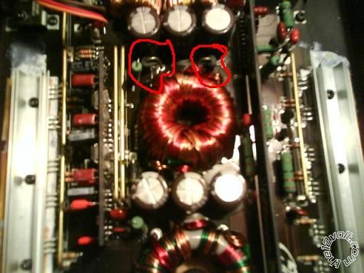
Hey I***t, there are two sets of two diodes that I think may be the ones. The diodes Im lookin for... will they have the symbol imprinted on the board?
.pg octane 900.5 repair - Page 6 -- posted image.
This is what I do for FUN!
i am an idiot 
Platinum - Posts: 13,667
Platinum spaceThis member consistently provides reliable informationspace
Joined: September 21, 2006
Location: Louisiana, United States
Posted: September 20, 2009 at 7:29 AM / IP Logged  

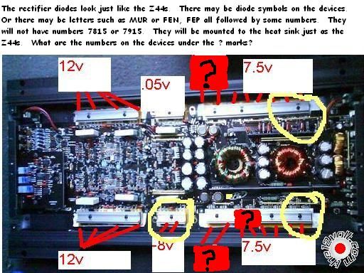
Sorry, the rectifier diodes are in the same case as the Z44s.  They are probably the next items in the row.  They will have either a picture of 2 diodes on each one.  One set of pictures will be pointing inward, and the other diodes will be pointing outward.  They may have the following letters all followed by some numbers.  FEN and FEP   or MUR.   The devices numbered 78XX and 79XX are not the diodes.  Do not remove them.  The 3 places that they may be located are labeled by the ? mark in the new red square on the picture.

pg octane 900.5 repair - Page 6 -- posted image.

Page of 8

  Printable version Printable version Post ReplyPost New Topic
You cannot post new topics in this forum
You cannot reply to topics in this forum
You cannot delete your posts in this forum
You cannot edit your posts in this forum
You cannot create polls in this forum
You cannot vote in polls in this forum

  •  
Search the12volt.com
Follow the12volt.com Follow the12volt.com on Facebook
Thursday, April 25, 2024 • Copyright © 1999-2024 the12volt.com, All Rights Reserved Privacy Policy & Use of Cookies
Disclaimer: *All information on this site ( the12volt.com ) is provided "as is" without any warranty of any kind, either expressed or implied, including but not limited to fitness for a particular use. Any user assumes the entire risk as to the accuracy and use of this information. Please verify all wire colors and diagrams before applying any information.

Secured by Sectigo
the12volt.com spacer
Support the12volt.com
Top
the12volt.com spacer