the12volt.com spacer
icon

viper 5101 8 pin connector


Post ReplyPost New Topic
< Prev Topic Next Topic >
shafferny 
Copper - Posts: 240
Copper spacespace
Joined: February 02, 2008
Location: New York, United States
Posted: February 02, 2010 at 5:09 PM / IP Logged  

Okay. From all the Googling I've done, this is what I've found. All the red wires go to +12v consant just as you said t&t tech! My connections should be as follows...

H3/1(Pink) ->RED / Blue @ Ignition Harness (+12v in the "run" and "start" position - typical ignition 1 wire)

H3/2(RED / White) ->N/A (+12v constant - polarity feed for the ignition 2/flex relay.)

H3/3(Orange) ->BLACK/ Orange @ Ignition Harness (+12v Accessory Output )

H3/4(Violet) ->Yellow @ Ignition Harness (+12v Stater Output/"Crank" wire)

H3/5(Red) ->(+12v constant- polarity feed for the Ignition 1 relay)

H3/6(Pink/White) ->N/A (Ignition 2/flex relay output)

H3/7(Pink/Black) ->N/A (flex relay input)

H3/8 (RED / Black)->(+12v constant - polarity feed to the accessory and starter relays)

I don't think I need the H3/2 since it is only the polarity feed for the ignition 2/flex relay. I won't be using it.

Assuming this is correct, would the Red & Pink/Black in the ignition harness be sufficient in size to power all the red since they are only polarity wires, or would I be safer off running a dedicated wire to power these three?

BTW, I'm not impressed with DEI, nor the place I purchased the car starter from. Neither will offer documents or diagrams for fear of liability. I understand their reason, but if it that was the case no one would ever sell car parts. lol 

shafferny 
Copper - Posts: 240
Copper spacespace
Joined: February 02, 2008
Location: New York, United States
Posted: February 02, 2010 at 5:12 PM / IP Logged  
The weird thing is, all the other wires/connections in the manual are pretty well laid out and logical.
t&t tech 
Platinum - Posts: 2,608
Platinum spacespace
Joined: October 05, 2008
Location: Trinidad and Tobago
Posted: February 02, 2010 at 6:04 PM / IP Logged  
The power wires at the ignition harness will suffice, you will also need to power that h3/2 wire!
commit your way to jehovah and he will act in your behalf. psalms 37:5
shafferny 
Copper - Posts: 240
Copper spacespace
Joined: February 02, 2008
Location: New York, United States
Posted: February 03, 2010 at 4:45 PM / IP Logged  

Really? I was thinking the H3/2 would only be needed if the H3/6 was going to be utilized.  Since my Jeep Liberty doesn't have a second ignition, accessory, or starter wire I didn't think I would be using it. I suppose it could be used for some other purpose as a "flex relay" if desired.

H3/2 - (+) FUSED (30A) FUSED IGNITION 2 /FLEX RELAY INPUT 87

This wire is the polarity feed for the ignition 2/flex relay.

H3/6 - IGNITION 2 / FLEX RELAY OUTPUT 30

This wire is factory programmed as Ignition 2 and can be programmed as a 2nd accessory or 2nd starter.

Am I thinking correctly here?

shafferny 
Copper - Posts: 240
Copper spacespace
Joined: February 02, 2008
Location: New York, United States
Posted: February 05, 2010 at 2:54 PM / IP Logged  
Anybody?
moonliter 
Copper - Posts: 322
Copper spacespace
Joined: February 28, 2007
Location: Canada
Posted: February 05, 2010 at 4:39 PM / IP Logged  

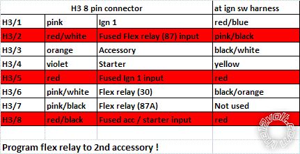
According to the wiring chart on your own post, this jeep has 2 +12v sources, 1 ign, 1 starter & 2 acc's. therefore you're going to use all the inputs and outputs (except H3/7) on the H3 8-pin connector. You'll have to program the flex relay from default 2nd ign to 2nd accessory.. see the chart below

viper 5101 8 pin connector - Page 2 -- posted image.

shafferny 
Copper - Posts: 240
Copper spacespace
Joined: February 02, 2008
Location: New York, United States
Posted: February 06, 2010 at 4:30 PM / IP Logged  

You're absolutely right moonliter. I don't know why I didn't see that. Thanks for the clarification.

I appreciate all the help I've recieved on this forum. Thank you!

smokeman1 
Platinum - Posts: 1,588
Platinum spaceThis member has made a donation to the12volt.com. Click here for more info.spaceThis member has been recognized as an authority in Mobile Security and Convenience. Click here for more info.spacespace
Joined: September 14, 2009
Location: Wisconsin, United States
Posted: February 08, 2010 at 11:47 AM / IP Logged  

guidance anyone,

I am looking for the same type of help with the same heavy gauge H3 8 pin connector for a 2005 Ford Focus. As Shaffnery wrote, the instructions are vague as to what and where.  I have a posting at   viper 5301on 2005 ford focus on this site looking for the same help.  On the 2005 focus wiring chart I have one 12 volt constant (red)(+), one starter (gray/black)(+), one ignition 1 (GREEN/ YELLOW(+), and one ACCESSORY /HEATER blower 1(yellow(+).  No second 12 volt constant, starter, ignition, or accessory wires on the car.

Thanks for looking

shafferny 
Copper - Posts: 240
Copper spacespace
Joined: February 02, 2008
Location: New York, United States
Posted: February 08, 2010 at 4:34 PM / IP Logged  

Judging from the wiring diagram I got from DEI, it looks like the Red & Pink/Black wire(the 12v constant in the ignition harness) powers the ignition wire, both accessory wires, and the starter wires. I think I'm going to tap into that to power the H3/2, H3/5, and H3/8.

shafferny 
Copper - Posts: 240
Copper spacespace
Joined: February 02, 2008
Location: New York, United States
Posted: February 09, 2010 at 4:18 PM / IP Logged  

After reading the topic below, I've decided to split up my power needs up like this..

.viper 5101 8 pin connector - Page 2 -- posted image.

 The +12v power wire for the primary harness(H1/2), will also be connected to Pink/Black in the ignition wire harness. I will use the red wire in the ignition harness to also power the Directed 457cw door lock interface I'm going to install(5amps at the most).

Both the red and pink/black wires in the ignition harness are 12gauge wires with 40A fuses each. I think things will be sufficient this way.

https://www.the12volt.com/installbay/forum_posts.asp?tid=85310&KW=tapping+ignition+wires 

Page of 4

  Printable version Printable version Post ReplyPost New Topic
You cannot post new topics in this forum
You cannot reply to topics in this forum
You cannot delete your posts in this forum
You cannot edit your posts in this forum
You cannot create polls in this forum
You cannot vote in polls in this forum

  •  
Search the12volt.com
Follow the12volt.com Follow the12volt.com on Facebook
Saturday, April 20, 2024 • Copyright © 1999-2024 the12volt.com, All Rights Reserved Privacy Policy & Use of Cookies
Disclaimer: *All information on this site ( the12volt.com ) is provided "as is" without any warranty of any kind, either expressed or implied, including but not limited to fitness for a particular use. Any user assumes the entire risk as to the accuracy and use of this information. Please verify all wire colors and diagrams before applying any information.

Secured by Sectigo
the12volt.com spacer
Support the12volt.com
Top
the12volt.com spacer