the12volt.com spacer
icon

remote start, 2010 toyota matrix


Post ReplyPost New Topic
< Prev Topic Next Topic >
kreg357 
Platinum - Posts: 7,783
Platinum spaceThis member has made a donation to the12volt.com. Click here for more info.spaceThis member has been recognized as an authority in Electrical Theory. Click here for more info.spaceThis member has been recognized as an authority in Mobile Security and Convenience. Click here for more info.spacespace
Joined: January 30, 2009
Location: Pennsylvania, United States
Posted: September 06, 2013 at 10:56 AM / IP Logged  
OK. ADS AL CA flashed with ADS AL(DL)-TL1 firmware, using guide #10731 and diagram on Page 6.
The answer to your question above is no.
A few points to mention.
1. If you will be connecting the bypass module to the CT-3310 remote start unit in the W2W mode, you must
     set the ADS AL CA module to the Install type = Standard setting ( two LED blinks ) and lock it in prior to
     programming the module to the vehicle. I usually just do a Factory Reset, set Install Mode and program
     to the vehicle all at once, in that order. These steps are listed on Page 13 and Page 11.
2. In W2W mode, you will follow the iDatalink install guide diagram on Page 6. You will make all the necessary
     wire connections between the two modules ( solid Black lines, solid Red lines and dashed Black lines ).
     Necessary refers to the fact that while shown, the Matrix does not have a trunk release, nor a Factory
     Hood Pin ( install the CT-3310 supplied hood pin). Additionally, the CT-3310 has no need for the Door Status,
     E-Brake or Trunk Status signals.
3. In W2W mode you will not use the ADS AL CA supplied D2D harness. Instead use the Black 4 pin connector
     harness that has three wires, Red, Black and Blue/White. These wires go to the CT-3310, +12V power,
     chassis ground and Ground When Running ( aka (-) Status Output ).
4. The ADS AL CA Pink wire gets connected to the CT3310 thick Ignition1 wire that continues to the Matrix's
      Ignition 1 wire.
5. The bypass module does supply a nice Tach Signal, so use that and run in Tach Mode for good reliability.
Any signal supplied by or handled by the bypass module does not have to be redundantly connected to the
Matrix. This includes the Lock/Arm, Unlock/Disarm, Tach and Brake signals for your R/S w/keyless install.   
The ADS bypass module does this thru the CAN data connections.
Soldering is fun!
mike31 
Copper - Posts: 75
Copper spacespace
Joined: January 14, 2009
Location: Ontario, Canada
Posted: September 06, 2013 at 7:45 PM / IP Logged  

HI Kreg

Thakn a lot for your response ,no doubt this is a great site with great and helpful people.

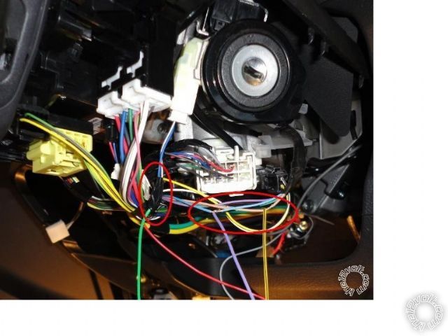
I am trying to locate the immobilizer on Matrix 2010 , it is a black connector with only 4 wires: violent,beige (light pink), light blue, green . It is located  at the end of the ignition key assembly and it is supposed to be 7 pin connector which  I can not see clearly. I wonder somebody can verify it if it is the one that I am seeing. Thanks Mike

kreg357 
Platinum - Posts: 7,783
Platinum spaceThis member has made a donation to the12volt.com. Click here for more info.spaceThis member has been recognized as an authority in Electrical Theory. Click here for more info.spaceThis member has been recognized as an authority in Mobile Security and Convenience. Click here for more info.spacespace
Joined: January 30, 2009
Location: Pennsylvania, United States
Posted: September 06, 2013 at 8:27 PM / IP Logged  
Here is a photo of the transponder wires from the 2009 Vibe Pictorial :
remote start, 2010 toyota matrix - Page 3 -- posted image.
Soldering is fun!
mike31 
Copper - Posts: 75
Copper spacespace
Joined: January 14, 2009
Location: Ontario, Canada
Posted: September 06, 2013 at 11:46 PM / IP Logged  
HI
Is ASD-ALCA needs to be fused and if so what should be ampere .
Thank you. Mike
kreg357 
Platinum - Posts: 7,783
Platinum spaceThis member has made a donation to the12volt.com. Click here for more info.spaceThis member has been recognized as an authority in Electrical Theory. Click here for more info.spaceThis member has been recognized as an authority in Mobile Security and Convenience. Click here for more info.spacespace
Joined: January 30, 2009
Location: Pennsylvania, United States
Posted: September 07, 2013 at 6:40 AM / IP Logged  
Personally, I never add a fuse to the thin ADS AL CA Red +12V power input wire. If you feel the need, a 3 Amp fuse would be my guess.
Soldering is fun!
mike31 
Copper - Posts: 75
Copper spacespace
Joined: January 14, 2009
Location: Ontario, Canada
Posted: September 10, 2013 at 11:07 PM / IP Logged  
HI
How do I do programming the 4 button transmitter and R/S itself. Now wiring is different .
Thanks a lot. Mike
mike31 
Copper - Posts: 75
Copper spacespace
Joined: January 14, 2009
Location: Ontario, Canada
Posted: September 10, 2013 at 11:32 PM / IP Logged  
I reviewed the Prostart manual and PAB can be used instead of the hood pin switch as long as hood is up (page 10) and follow the rest of the procedure ,but at the same time the hood pin switch is not connected to R/S but to ASD-ALCA ORANGE / black wire as (-) input.
I am not really sure if it works.Mike
kreg357 
Platinum - Posts: 7,783
Platinum spaceThis member has made a donation to the12volt.com. Click here for more info.spaceThis member has been recognized as an authority in Electrical Theory. Click here for more info.spaceThis member has been recognized as an authority in Mobile Security and Convenience. Click here for more info.spacespace
Joined: January 30, 2009
Location: Pennsylvania, United States
Posted: September 11, 2013 at 6:25 AM / IP Logged  
I am a bit confused. It seems your connections concerning the Hood Pin Switch are wrong.
Here is the way it works ( the long story ).
On vehicles that have a Factory Hood Pin Switch installed, the ADS AL CA with DL TL1 firmware will obtain
the hood pin info from the vehicle via the CAN Bus data connection and supply that information to the R/S
( CT-3310 in your case ) through the Yellow wire ( shown as a Red line in the install diagram ). If the vehicle
does not have a Factory Hood Pin Switch, the AD AL CA ORANGE / Black wire must be grounded and the Yellow
wire won't used / connected because it is not able to supply any Hood Pin Status Info. In this case, a after-
market hood pin switch should be installed and it's signal wire directly connected to the R/S ( CT-3310 for you ).
The short story :
Your vehicle did not come with a Factory Hood Pin Switch ( I'm assuming you checked ).
The ADS AL CA w/DL TL1 firmware is not able to supply a Hood Status Output.
The ADS AL CA ORANGE / Black wire is connected to Chassis Ground.
The ADS AL CA Yellow wire is not used / connected.
An after-market hood pin switch will be installed in the car. It's signal wire will be connected directly to the
      CT-3310 5-Pin Secondary Harness, Pin 3, Grey wire.
With the Hood Pin Switch installed and connected directly to the CT-3310, you should have no problems
programming the remotes and setting the other programming options using either the hood pin switch
or the PAB ( with the hood up ).
Soldering is fun!
mike31 
Copper - Posts: 75
Copper spacespace
Joined: January 14, 2009
Location: Ontario, Canada
Posted: September 11, 2013 at 8:51 AM / IP Logged  
HI
Thank you Kreg for clarification.I thought hood pin switch is connected directly to ORANGE / black wire.Looking at page 6 of the Idatalink wiring diagram(type one)shows no direct connection from R/S to hood pin switch in compare to parking light connection. Mike
mike31 
Copper - Posts: 75
Copper spacespace
Joined: January 14, 2009
Location: Ontario, Canada
Posted: September 13, 2013 at 1:25 AM / IP Logged  
Hoping to be my final question
system : Prostart CT-3310 remote starter, Idatalink (ASD-AL CA),Toyota Matrix 2010
HI
I have prepared R/S and ASD-AL CA to be connected to Matrix wiring system . I am certain that only ignition wire #1 (brown to pink wire of the ASD-AL CA to ignition wire of R/S) and starter wire #1 (black)to R/S, but what about ignition wire #2, starter #2.
I think they are NOT required to be connected to any external circuit
Please advice
Thank you . Mike
Page of 7

  Printable version Printable version Post ReplyPost New Topic
You cannot post new topics in this forum
You cannot reply to topics in this forum
You cannot delete your posts in this forum
You cannot edit your posts in this forum
You cannot create polls in this forum
You cannot vote in polls in this forum

  •  
Search the12volt.com
Follow the12volt.com Follow the12volt.com on Facebook
Sunday, May 5, 2024 • Copyright © 1999-2024 the12volt.com, All Rights Reserved Privacy Policy & Use of Cookies
Disclaimer: *All information on this site ( the12volt.com ) is provided "as is" without any warranty of any kind, either expressed or implied, including but not limited to fitness for a particular use. Any user assumes the entire risk as to the accuracy and use of this information. Please verify all wire colors and diagrams before applying any information.

Secured by Sectigo
the12volt.com spacer
Support the12volt.com
Top
the12volt.com spacer