the12volt.com spacer
icon

Door popping circuit


Post ReplyPost New Topic
< Prev Topic Next Topic >
auex 
Platinum - Posts: 5,041
Platinum spaceThis member has made a donation to the12volt.com. Click here for more info.spacespace
Joined: December 23, 2002
Location: Arizona, United States
Posted: July 22, 2005 at 4:45 PM / IP Logged  
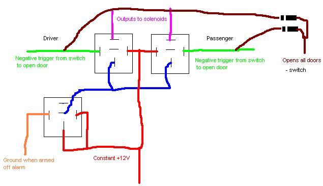
Door popping circuit - Page 5 -- posted image.
Certified Security Specialist
Always check info with a digital multimeter.
I promise to be good.
Tell Darwin I sent you.
I've been sick lately, sorry I won't be on much.
paulieA 
Member - Posts: 32
Member spacespace
Joined: July 21, 2005
Location: United Kingdom
Posted: July 22, 2005 at 4:56 PM / IP Logged  

ah, thanks for your time. Im affraid i cant follow that diagram. As i said, im new to electronics and have never used a relay before, so all the pins mean nothing to me. I dont know the diffrence and what each one does.

All i know is, i want a button on the outside of my car that will only operate when the keyfob has been pressed, and will not work any of the other time.

auex, does this system above work as the keyfob remote only sends a short pulse through to the solenoids.

Hello!!!
paulieA 
Member - Posts: 32
Member spacespace
Joined: July 21, 2005
Location: United Kingdom
Posted: July 22, 2005 at 5:11 PM / IP Logged  

i do like the idea's, but i just dont understand. Im sorry if this offends, i was just told by a friend that this forum is very helpful when it comes to technical help.

Im just looking for a solution to my problem is all, and i cant understand the above diagram as its just coloured lines to me, id need some helpful explanations with it for a newbie like myself.

Hello!!!
paulieA 
Member - Posts: 32
Member spacespace
Joined: July 21, 2005
Location: United Kingdom
Posted: July 22, 2005 at 5:27 PM / IP Logged  

its not that i dont want an alarm that has this function, its the fact that in the UK you need a button on the outside of the car.

Simply having the door pop open from a remote is not enough to pass the safety test you have to take each year, so the car wont be legal. If the cops pull you over, they check all the documents and if you dont have the safety certificate then you will lose your license. I hope this explains it a bit better.

So i need a button on the outside, but not one that works when im not at the car otherwise anyone will just press it and be able to jump in.

Because the remote keyfob button only sends a pulse through the system, just having a normal relay is not good enough as it will click over when it pulses, but then click back straight away again. I need something that will click over with the pulse, and then stay there.

Hello!!!
paulieA 
Member - Posts: 32
Member spacespace
Joined: July 21, 2005
Location: United Kingdom
Posted: July 22, 2005 at 5:41 PM / IP Logged  

that is what i want to do bobk.

Press the remote key fob button which then enables the door popping circuit, allowing me to push a button on the outside of the car to gain entry.

If the remote key fob button has not been pressed, then the button on the outside of the car will do nothing.

Its the help with the relay's i need, as i dont know how to set them up to achive my task. I was under the impression that just a pulse from the remote key fob circuit will go through the relay, click it over, and then once the pulse has passed it will immediately click back over. This will only give me a spilt second to press the button on the outside of the car, which will not be good enough.

I hope this explains things a bit better.

Hello!!!
paulieA 
Member - Posts: 32
Member spacespace
Joined: July 21, 2005
Location: United Kingdom
Posted: July 22, 2005 at 9:23 PM / IP Logged  

Can anyone look at my resived diagram below, and tell me if it will work. I have incorporated a standard relay and i think this might cure my problem of the timer shutting down the system once i am in the car and driving. Thanks for all your help on this.

Door popping circuit - Page 5 -- posted image.

Hello!!!
Powermyster 
Silver - Posts: 962
Silver spacespace
Joined: April 06, 2005
Location: Ireland
Posted: July 23, 2005 at 6:29 AM / IP Logged  
i can't follow your diagrams.   but get this.. Use the time like a was saying then use another SPDT RElay off the ignition harness to bypass the micto switch again.
 
 
so what will happen is that you will press the fob. and you have 60 to press the button to open the door.
 
the once you start the car the circuit is always complete. then switch off the ignition and is cun gain..
 
 
use the timer to gain entry and a standard relay for when the ign is on
paulieA 
Member - Posts: 32
Member spacespace
Joined: July 21, 2005
Location: United Kingdom
Posted: July 23, 2005 at 7:02 AM / IP Logged  

hi Powermyster. Sorry if you cant follow my diagrams, i dont know how to draw electrical diagrams properly.

But what you have said above is exactly what my diagram shows! The normal relay comes from the ignition which then bypasses the timer circuit meaning the popping circuit is always open when the igntion is on. If the ignition is off, then the interal buttons still work, but the external buttons only work once the keyfob has been pressed.

I think this is my final design.

Hello!!!
Powermyster 
Silver - Posts: 962
Silver spacespace
Joined: April 06, 2005
Location: Ireland
Posted: July 23, 2005 at 7:47 AM / IP Logged  
good man
Powermyster 
Silver - Posts: 962
Silver spacespace
Joined: April 06, 2005
Location: Ireland
Posted: July 23, 2005 at 7:49 AM / IP Logged  
p.s what are you using to draw the diagrams they are looking very neat
Page of 6

  Printable version Printable version Post ReplyPost New Topic
You cannot post new topics in this forum
You cannot reply to topics in this forum
You cannot delete your posts in this forum
You cannot edit your posts in this forum
You cannot create polls in this forum
You cannot vote in polls in this forum

  •  
Search the12volt.com
Follow the12volt.com Follow the12volt.com on Facebook
Monday, April 29, 2024 • Copyright © 1999-2024 the12volt.com, All Rights Reserved Privacy Policy & Use of Cookies
Disclaimer: *All information on this site ( the12volt.com ) is provided "as is" without any warranty of any kind, either expressed or implied, including but not limited to fitness for a particular use. Any user assumes the entire risk as to the accuracy and use of this information. Please verify all wire colors and diagrams before applying any information.

Secured by Sectigo
the12volt.com spacer
Support the12volt.com
Top
the12volt.com spacer