the12volt.com spacer
icon

2000 Neon, Viper 5900 sst


Post ReplyPost New Topic
< Prev Topic Next Topic >
Big Dog 
Gold - Posts: 1,265
Gold spaceThis member consistently provides reliable informationspace
Joined: May 02, 2002
Location: Quebec, Canada
Posted: November 17, 2006 at 10:10 AM / IP Logged  

Sorry I didn't get back to you sooner......too busy.

Don't connect the BLACK/ White second accessory. This only feeds the radio and wipers (not required for remote start)

For locks, don't use the two relay 5 wire reversal method you show above.

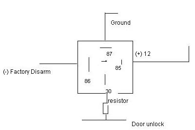
Look for a Light Green wire coming from the drivers door harness. Use the Factory ARM and Factory Disarm for lock/unlock. Relays are required for both lock and unlock.  If vehicle has factory alarm, use negative trigger thru a 2.7K ohm resistor for arm/lock, and negative thru a 7.5K ohm resistor for disarm/unlock, use double pulse for unlock. If there is no factory alarm then Lock is negative trigger thru a 1K ohm resistor, unlock is negative thru a 250 ohm resistor.

For the door pin input, use the Green zone 3 in the main harness. Use tan in the drivers kick for the drivers door and blue/orange in the passengers kick for the passengers door. Both wires are negative trigger and must be diode isolated.

For trunk pin use the Blue zone 4 input (negative) and connect to the tab/black at the trunk light.

For hood pin use the small gray hood shut down input. Install your own.

You don't connect the domelight supervision nor the armed out wires of the 5900.

Prepare your future. It wasn't the lack of stones that killed the stone age.
m2736185 
Member - Posts: 45
Member spacespace
Joined: October 30, 2006
Location: United States
Posted: November 18, 2006 at 11:19 AM / IP Logged  

thanks for the reply, let me make sure i got this right.. so I use a relay for the door locks so i solder the wiring coming OUT of the relay not before to a resistor then solder the other end of the resistor to the door unlock wire? And how would I use double pulse?

2000 Neon, Viper 5900 sst - Page 2 -- posted image. 

Now for the door pin I run a wire from the blue/orange  then one from the ran connect a resistor to each of the ends then connect the other end to the alarm input? I can use a 3 amp resistor right?

m2736185 
Member - Posts: 45
Member spacespace
Joined: October 30, 2006
Location: United States
Posted: November 19, 2006 at 1:11 PM / IP Logged  
btw what resistors am I using, (3/4w, 1w?) and what tolerance, 5%,`%?
daxton 
Member - Posts: 14
Member spacespace
Joined: December 16, 2002
Location: Canada
Posted: November 19, 2006 at 11:42 PM / IP Logged  
does anyone have the pdf install manual for the 5900? wanted to have a read through it, but can't find online.
thanks
dax
Big Dog 
Gold - Posts: 1,265
Gold spaceThis member consistently provides reliable informationspace
Joined: May 02, 2002
Location: Quebec, Canada
Posted: November 20, 2006 at 8:20 AM / IP Logged  
It's exactly the same as this https://www.the12volt.com/installbay/file.asp?ID=430 execpt that it uses a different antenna and transmitter frequency. Functions on TX are the same.
Prepare your future. It wasn't the lack of stones that killed the stone age.
Big Dog 
Gold - Posts: 1,265
Gold spaceThis member consistently provides reliable informationspace
Joined: May 02, 2002
Location: Quebec, Canada
Posted: November 20, 2006 at 8:22 AM / IP Logged  
m2736185, your doorlock diagram is correct. One relay for arm/lock and one for disarm/unlock. 1/4 watt 10% resistors are fine.
Prepare your future. It wasn't the lack of stones that killed the stone age.
m2736185 
Member - Posts: 45
Member spacespace
Joined: October 30, 2006
Location: United States
Posted: November 23, 2006 at 1:44 AM / IP Logged  
For the door locks, there is no Neg Green lock unlock, i think the door locks=5 wire door lock
Big Dog 
Gold - Posts: 1,265
Gold spaceThis member consistently provides reliable informationspace
Joined: May 02, 2002
Location: Quebec, Canada
Posted: November 23, 2006 at 8:12 AM / IP Logged  
In that case it's ORANGE / black and pink/black - 5 wire reversal. Follow the diagram you showed us in your second post. Be sure that the tracers are black - not purple, because under certain lights they can look similar.
Prepare your future. It wasn't the lack of stones that killed the stone age.
m2736185 
Member - Posts: 45
Member spacespace
Joined: October 30, 2006
Location: United States
Posted: November 23, 2006 at 4:50 PM / IP Logged  
Do you know where the wires are located? I cut a orange black wire and a pink violet wire in the kick panel and it stopped the back door locks from working. I guess i need to find the wire going from the switch to the motor.
Big Dog 
Gold - Posts: 1,265
Gold spaceThis member consistently provides reliable informationspace
Joined: May 02, 2002
Location: Quebec, Canada
Posted: November 24, 2006 at 7:20 AM / IP Logged  

m2736185 wrote:
For the door locks, there is no Neg Green lock unlock, i think the door locks=5 wire door lock

I'm sorry to be a pain about this but I'm convinced you can do it multiplexed.

Do you have a doorlock switch on the driver's door? Does it lock and unlock all? Does the key in the driver's door lock/unlock all? Do you have an OEM alarm? Then it's a single wire multiplex and the green wire has to be there. It runs from the driver's door to a module in the center dash above the heating controls.

The pink/purple wire you cut is the "unlock" motor wire for three doors and will not control the driver's door. That's why I mentioned "black tracer" not purple. BTW, it also runs up to that module in the dash.

Prepare your future. It wasn't the lack of stones that killed the stone age.
Page of 5

  Printable version Printable version Post ReplyPost New Topic
You cannot post new topics in this forum
You cannot reply to topics in this forum
You cannot delete your posts in this forum
You cannot edit your posts in this forum
You cannot create polls in this forum
You cannot vote in polls in this forum

  •  
Search the12volt.com
Follow the12volt.com Follow the12volt.com on Facebook
Sunday, April 28, 2024 • Copyright © 1999-2024 the12volt.com, All Rights Reserved Privacy Policy & Use of Cookies
Disclaimer: *All information on this site ( the12volt.com ) is provided "as is" without any warranty of any kind, either expressed or implied, including but not limited to fitness for a particular use. Any user assumes the entire risk as to the accuracy and use of this information. Please verify all wire colors and diagrams before applying any information.

Secured by Sectigo
the12volt.com spacer
Support the12volt.com
Top
the12volt.com spacer